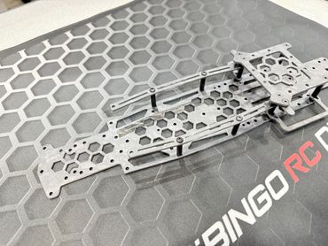
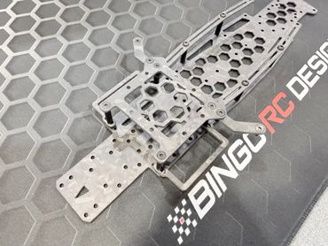
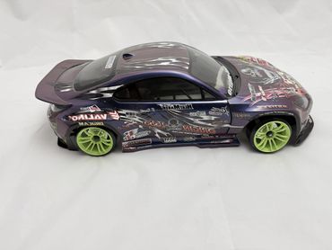
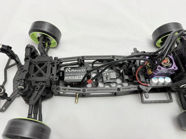
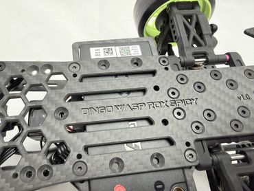
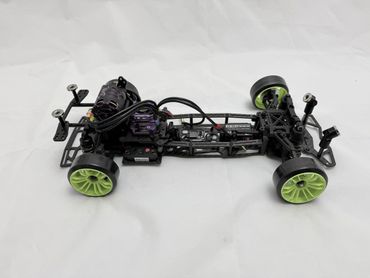
Bingo Wasp RDX Spicy Chassis
The Bingo Wasp RDX Spicy Chassis is a new variant of the Bingo Wasp RDX chassis. It integrates the Bingo Wasp RDX Battery Tray and uses side rails to create a more rigid structure. This chassis is compatible with the stock ReveD RDX, ReveD MC3, and the Team ADX front and rear components.
(name inspired by ReveD Team Driver Adam Torres IG @mr.spicy_rd)

Bingo Wasp RDX Spicy Assembly Instructions
Step 1. Assembly Battery Lock Arms

Assemble both battery lock arms as shown. Use M3x6 FHS x 2, and 5mm threaded standoff x 2. The standoffs are used to lock shorty thin batteries. If using shorty thick batteries, skip this step.
Step 2. Attach lock arms to top plate

Attach the lock arms to the top plate using a M3x10 FHS, 1mm spacer, and nylon lock nut.
Step 2a. Lock Arms Close Up

Lock Arms close up view. Install the 1mm spacer between the lock arm and the top plate. If using shorty thick batteries, do not install the 1mm spacer.
Step 2b. Lock Arms installed

Tighten the locknuts, but make sure the lock arm moves freely. It will hold open and closed using the magnets.
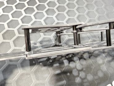
Step 3. Install side rail posts
Step 3a. Side rail posts installed

Install side rail posts as shown, 20mm threaded standoff x 4 and M3x8 FHS x 4.
Step 3a. Side rail posts installed
Step 3a. Side rail posts installed
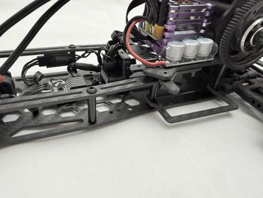
The 20mm side rail posts installed.
Step 4. Front battery gate posts
Step 4a. Front and Rear battery gate posts
Step 4. Front battery gate posts
Install the two front battery gate posts. Uses the two battery end gates, M3x12mm FHS x 2, 3mm spacer x 2, 15mm threaded standoff x 2. The 3mm spacer goes under the end gates. Screw the 15mm threaded standoff on top.
Step 4. Rear battery gate posts
Step 4a. Front and Rear battery gate posts
Step 4. Front battery gate posts
Install the two rear battery gate posts. Uses M3x12mm FHS x 2, 3mm spacer x 2, 22mm threaded standoff x 2. Like the front, the 3mm spacer goes under the end gate, screw the 22mm threaded standoff on top.
Step 4a. Front and Rear battery gate posts
Step 4a. Front and Rear battery gate posts
Step 4a. Front and Rear battery gate posts
Front and rear battery end gate posts installed.
Step 5. Install side rails
Step 5b. Side rails installed
Step 4a. Front and Rear battery gate posts
Install the left and right side rails using M3x8 BHS.
Step 5a. Side rail cutouts
Step 5b. Side rails installed
Step 5b. Side rails installed
Make sure the side rail cutouts are face down, and toward the rear of the chassis.
Step 5b. Side rails installed
Step 5b. Side rails installed
Step 5b. Side rails installed
The installed side rails should look like the image above.
Step 6. Side rail top spacers
Step 6. Side rail top spacers
Step 6. Side rail top spacers

Place the two 5mm spacers on top of the side rails, on the front battery gate post location.
Step 7. Add Top Plate
Step 6. Side rail top spacers
Step 6. Side rail top spacers
Attach the top plate. Use M3x8 FHS screws on the rear posts. Use M3x12 FHS screws on the front posts.
Step 7a. Lock arms open
Step 8. Adjust Battery End Gates
Step 8. Adjust Battery End Gates
Test that the lock arms can move freely from open to close. They should hold their position using the embedded magnets.
Step 8. Adjust Battery End Gates
Step 8. Adjust Battery End Gates
Step 8. Adjust Battery End Gates
Adjust the battery end gates to match your battery side. Loosen the 4 screws on the bottom, adjust the end gate, then re-tighten screws. Leave a little extra clearance so the battery to be removed easily.
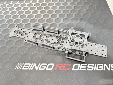
Bingo Wasp RDX Spicy Chassis